Face Shield

Hervorgehoben

Sources

GitLab Project at https://gitlab.com/HerrRausB/faceshield
Clone from GitLab: https://gitlab.com/HerrRausB/faceshield.git
Use Fusion 360 Model: https://a360.co/3aC6XjV

Description

Yet another face shield holder inspired by https://www.thingiverse.com/thing:4233193. I redesigned the entire thing aiming for more stability.

Customizing and assembly

You can open the Fusion 360 Model directly at Autodesk’s project hub or alternatively download the f3d export file from my GitLab repository.
Using Fusion 360 this version of the face shield also is highly customizable – especially through the parameter HeadDiameter.
I printed the part as well in PETG as an PLA – slicing and printing parameters depend on your respective machine and experience. Print time here is around 2:45h using an I3 clone at an avarage speed of 40-50mm/s and a layer height of 0.3mm.
As face shield I used a usual lamination slide, which I laminated empty. It seems to be quite stable. The slide then is fit into the slit around the outer perimeter of the holder. The slit internally is slightly concave so the slide should be held in place properly.
The holder is designed to be attached to the head using common 20mm wide rubber band for sewing – you can modify the respective width paramters in Fusion 360.

Pre rendered STL files

I rendered STL files for head sizes from 120mm through 160mm in 5mm steps for convenient use and those who don’t have access to Fusion 360.

Stay healthy and stay home! 🙂

Don’t use this model for commercial purposes! Otherwise you immediately will lose face and this shield wont protect you from social damage!


KSGER T12 Soldering Station

Public Fusion360 model
STL files on MyMiniFactory

Recently those KSGER T12 soldering stations and kits became very popular, so I ordered the controller, a pre-fitted handle, a 24V 3A power supply, an IEC320 connector, a cheap solder iron stand and some T12 Tips from AliExpress.

In addition I used 0.75mm² and 0.25mm² wire, crimp connectors, and a JST HC 5 pin connector and header for wiring up all electrical connections. I used a 1A fuse for the IEC320 connector’s integrated fuse socket.

Modeling and printing a case

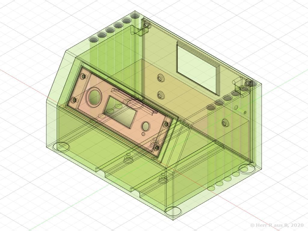
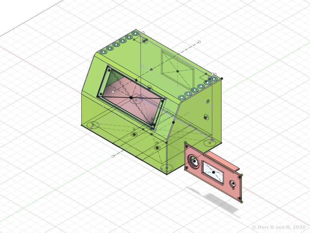
I constructed a case to house all the components using Fusion360…

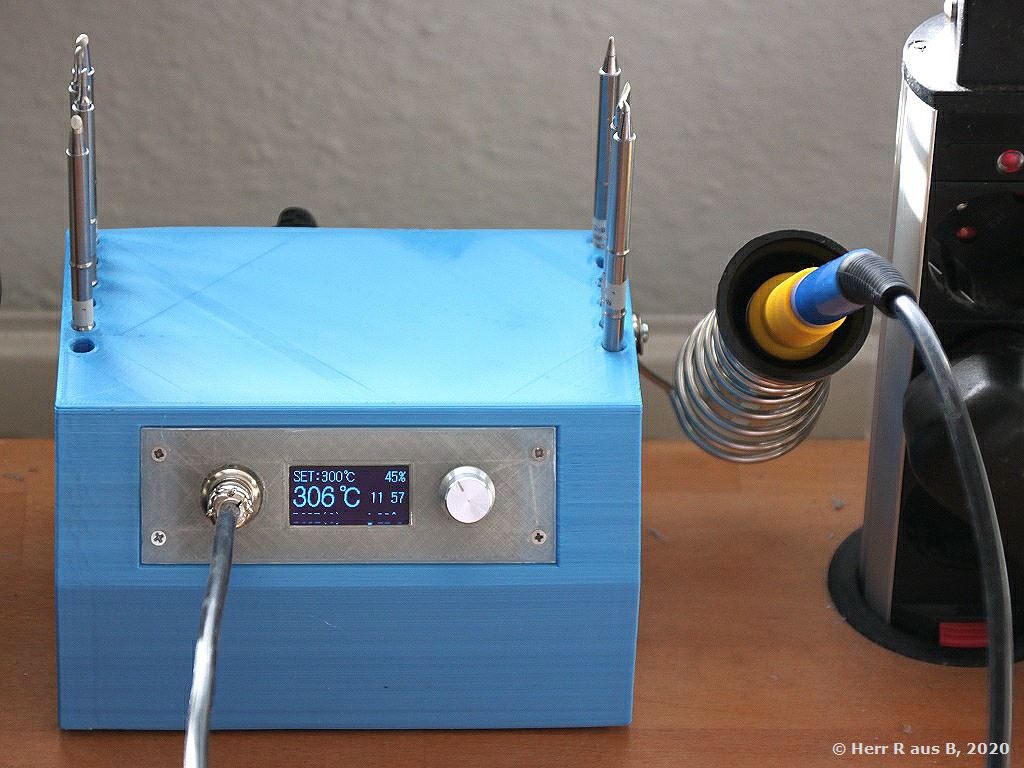
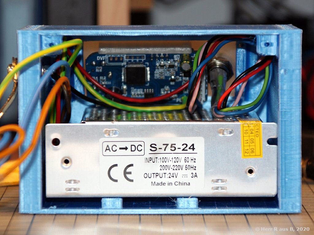
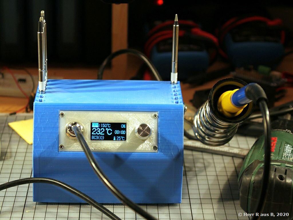
…printed it on my I3 3D printer and mounted everything:

I made the model public, so you can download and adapt it to your needs. Also, the STL files can be obtained at MyMinifactory.

Preparing the Controller

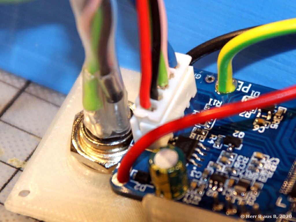
The actual construction of the controller PCB is rather strange as you would have to mount the 5 pin connector for the soldering tip somewhere and then solder the controller board to that connector. As the nut for fixing the connector to what ever panel used is on the inside of said panel. One then wouldn’t be able to remove the controller from wherever it is mounted to.

So I bravely took a heck saw and cut that part off the controller board. I then soldered a 5 pin JST header to the controller board and crimped the respective wires to the JST connector and soldered them to the 5 pin soldering tip connector – this also allows for moving the soldering tip connector away from the controller board – or as in this case even a little bit closer to it:

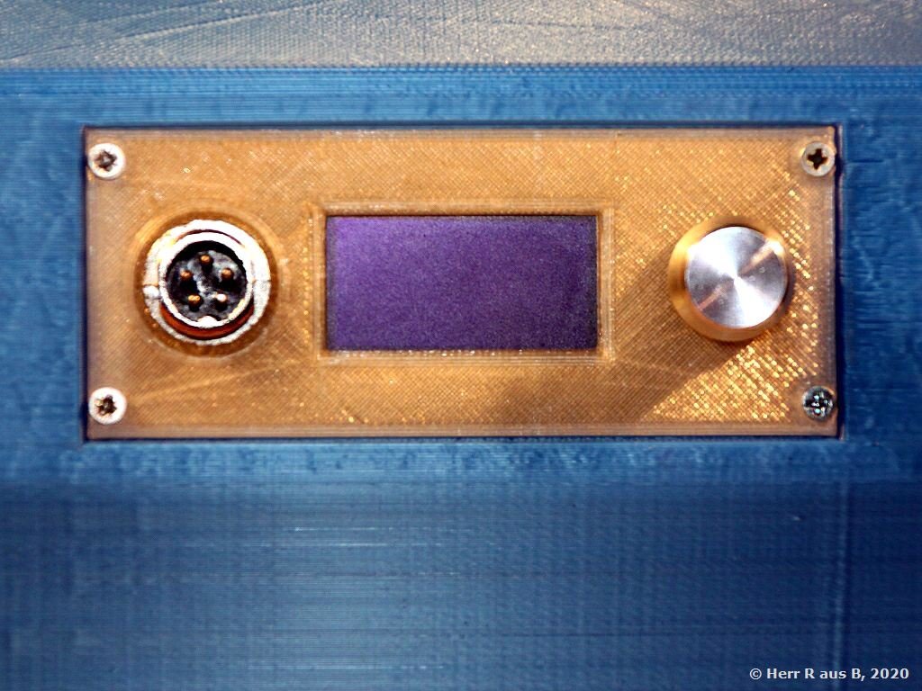
Note, that the unmodified control board wouldn’t fit the control panel as curently modelled, as the opening for the 5 pin solder tip connector is too close to the opening for the display!
Preparing the wiring

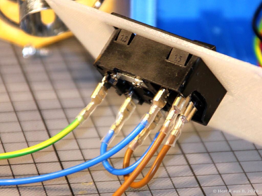
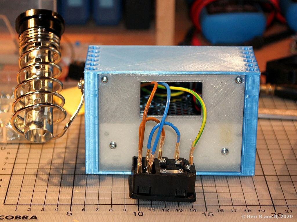
Crimp all wires for the IEC320 connector:

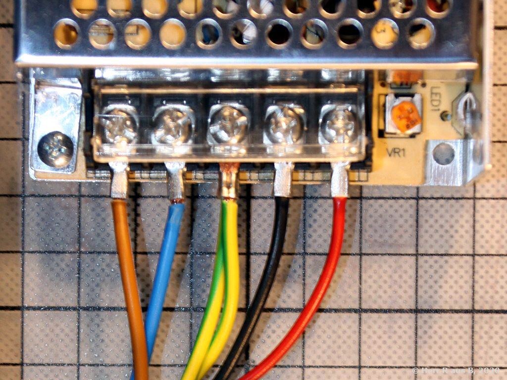
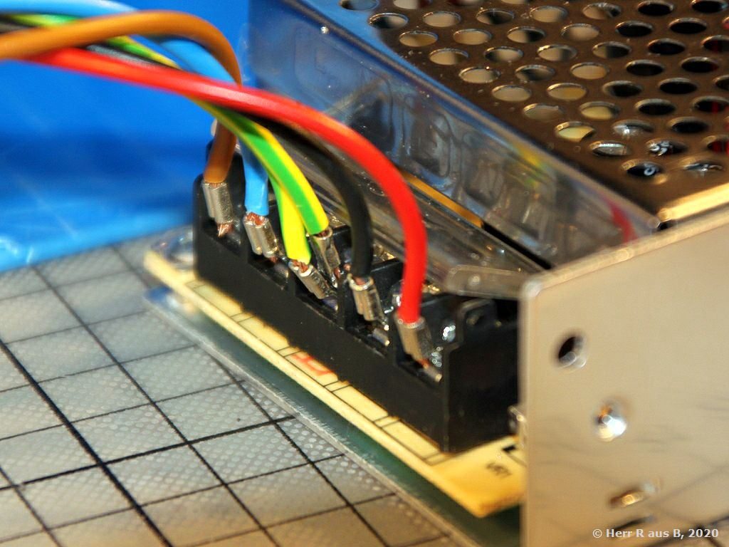
Crimp und connect all wires to the power supply. Make sure, you thread the wires for the controller through the opening in the case first!

All wires then need to be bend upwards carefully, because otherwise the power supply wouldn’t fit into the case:

Fitting everything together

Insert the control panel into the case and lock it in place using some 2mm wood or metal screws:

Slide the power supply into the case from the back…

…and lock it down from the bottom using three M3 screws:

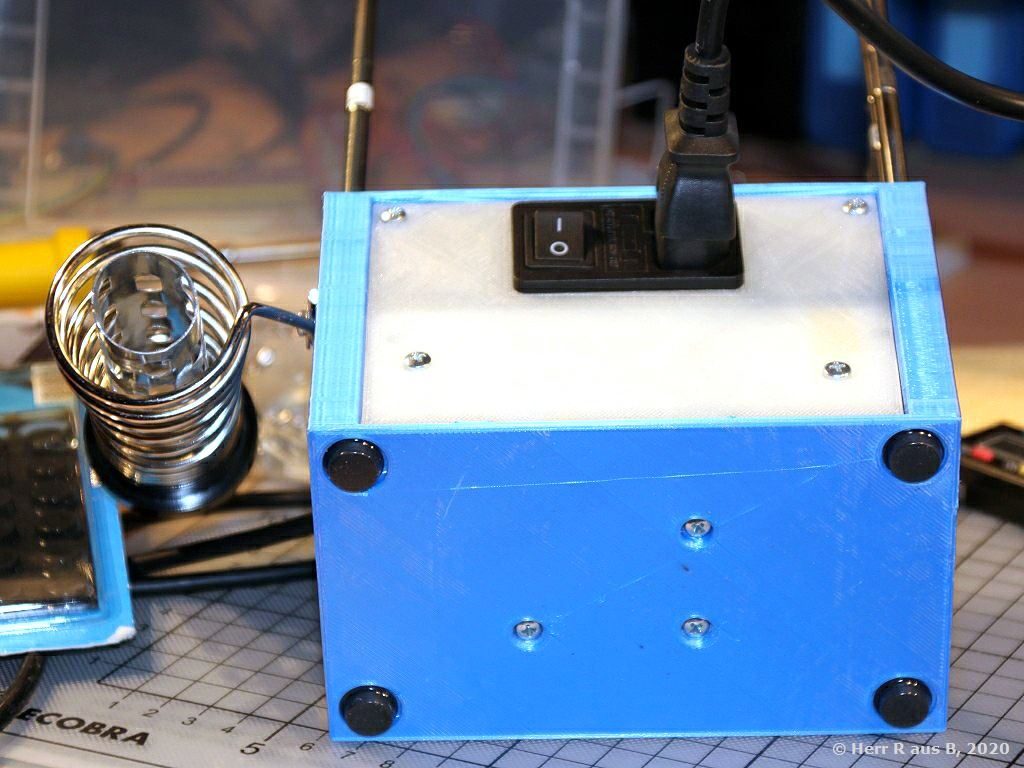
You might also want to apply some glide protection feet to the bottom of the case – the indents have a diameter of 14mm.

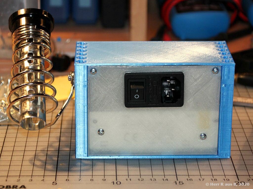
Mount the back plate to the case by fixing it to the power supply using two M3 screws and to the upper mounting points of the case using two 2-3mm wood or metal screws:

Mount the IEC320 connector by snapping it into the back plate in an orientation that suits your needs:

Mounting a solder tip holder

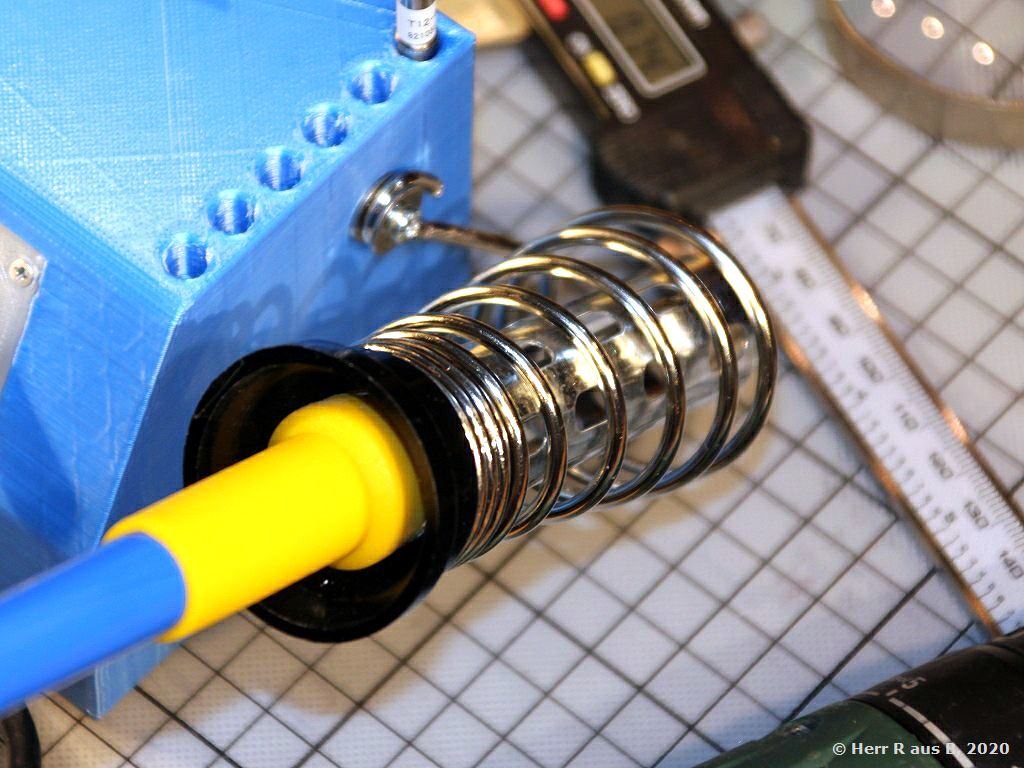
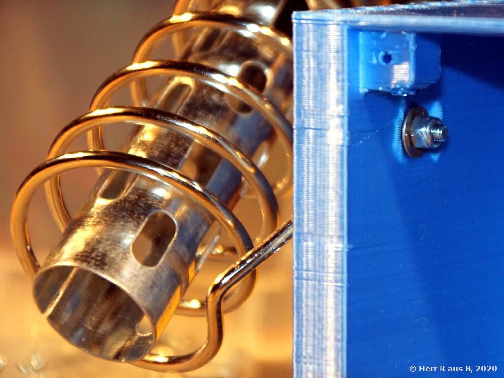
Mounting the solder tip holder is optional – the case has a 3mm through hole at the right side. I used an M3 screw, an M3 lock nut, and some washers to mount that cheap holder, I found on amazon:

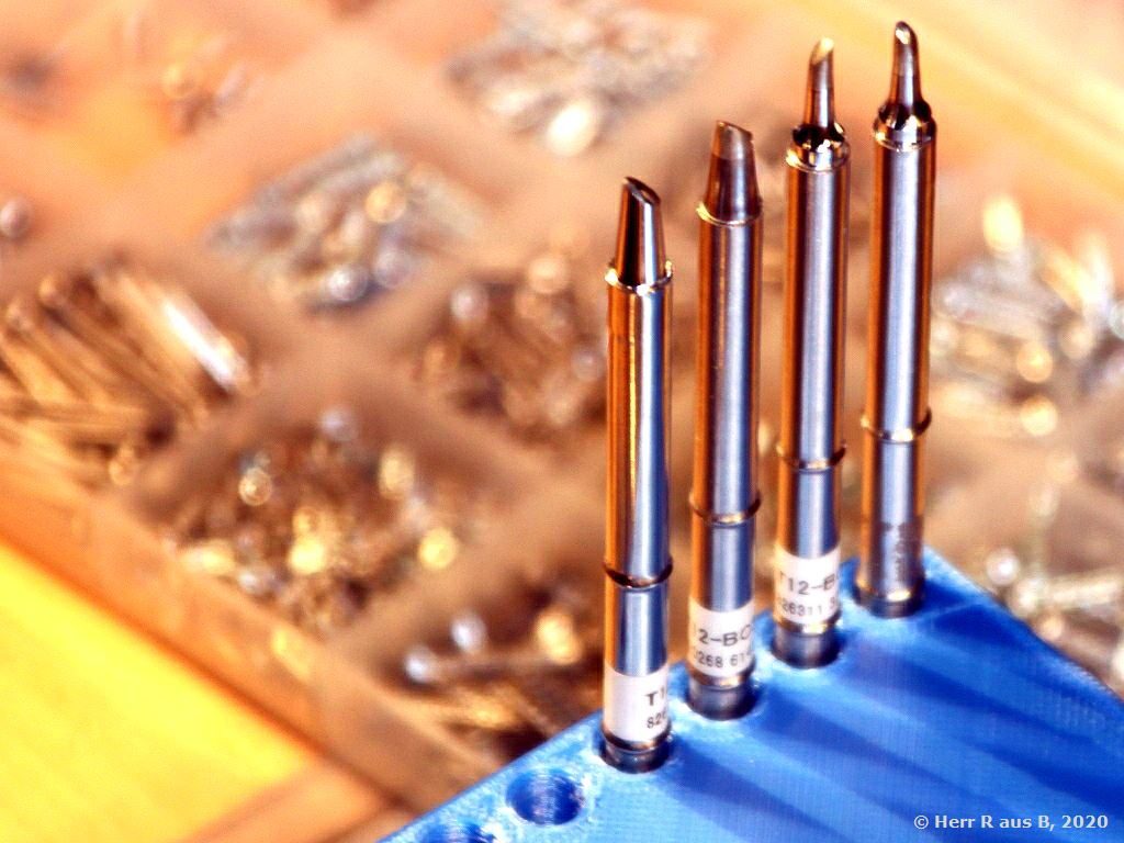
The case of the station also provides 12 inserts to store your T12 tips not in use:

Using the station

The station should now be ready for use – as there can be found tons of videos discussing these KSGER controllers on YouTube, I reccomend you just click here 🙂